F-shaped PCB antenna wiring
Introduction
Printed Circuit Board (PCB) antennas are widely used in various applications such as radio-frequency identification (RFID) systems, wireless communication systems, and other modern technologies including ZigBee, Bluetooth, and Wi-Fi. PCB antennas offer several advantages over other types of antennas such as small size, low cost, and easy integration. In this article, we will discuss how to connect an F-shape PCB antenna.
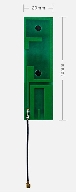
F-shape PCB Antenna
F-shape PCB antenna is a type of PCB antenna that resembles the letter \"F\" and is designed to operate in the frequency range of 2.4GHz to 2.5GHz. This antenna is widely used in wireless communication systems such as Bluetooth and Wi-Fi. It is easy to fabricate on a PCB using standard PCB fabrication techniques and can be integrated with other components on the same PCB.
Connecting the F-shape PCB antenna
The F-shape PCB antenna has two connectors, one for transmission and one for reception. The transmission connector is connected to the output of the RF transmitter, and the reception connector is connected to the input of the RF receiver. The F-shape PCB antenna also requires a ground connection for proper operation.
Connecting the transmission connector
The transmission connector of the F-shape PCB antenna should be connected to the output of the RF transmitter. This can be done by soldering a wire from the output of the RF transmitter to the connector on the PCB. Make sure that the wire is properly soldered and does not come loose. A loose wire can cause poor performance or even damage to the PCB antenna.
Connecting the reception connector
The reception connector of the F-shape PCB antenna should be connected to the input of the RF receiver. This can be done by soldering a wire from the input of the RF receiver to the connector on the PCB. Make sure that the wire is properly soldered and does not come loose. A loose wire can cause poor performance or even damage to the PCB antenna.
Connecting the ground
The F-shape PCB antenna requires a ground connection for proper operation. The ground connection can be provided through an unbroken copper plane on the PCB or by soldering the ground pin of the RF transmitter and receiver to the ground plane on the PCB. Make sure that the ground connection is properly made and does not have any breaks.
F-shape PCB antennas are widely used in wireless communication systems due to their small size, low cost, and easy integration. Connecting the F-shape PCB antenna involves connecting the transmission and reception connectors of the antenna to the output of the RF transmitter and input of the RF receiver, respectively. Additionally, the ground connection should be properly made for proper operation of the antenna. Proper connection and operation of the F-shape PCB antenna can ensure reliable and efficient wireless communication systems.
